{{schematic}} if possible.Redstone circuitry is a feature of Beta (and future versions of it) which allows for intricate Redstone wire based mechanisms to be created by players.
Advanced Redstone circuitry may be seen as comparable to the "WireMod" addon popular within Garry's Mod and to digital electronics in real life.
Logic Gates
A logic gate can be thought of as a simple device that taking one or more inputs will return an output decided upon from the inputs according to the rule that that logic gate follows. For example if both inputs on an AND gate are in the 'true'/'on'/'powered' state the gate will return 'true'/'on'/'powered'. Much more in-depth information and a better explanation of this expansive topic is available on Wikipedia.
Below is a list of some of the basic gates with example images and MC Redstone Sim diagrams. There are many different ways to construct them other than those shown below, so use them as guidelines for creating one to fit your needs.
Basic logic gate diagrams
Circuit Symbols
Each symbol represents one or two blocks (one represents three), viewed from above. All descriptions are with reference to a "ground level".
Redstone simulator symbol guide
From left to right:
- Air: air over air, i.e. two empty blocks, one above the other above ground level
- Block: air over a block (of any sort)
- Two Blocks: block over block, i.e. two solid blocks above ground level
- Wire: wire (with a block assumed to below the wire, below ground level)
- Redstone Torch: air over redstone torch (all torches are redstone torches in circuits)
- Wire on top of Block
- Torch over Block
- Block over Wire (i.e. the wire has an air block just above it; blocks cannot be put directly on wire)
- Block over Torch
- Torch over Wire (i.e. the wire has an air block just above it, the torch is above this)
- Bridge: wire on top of block, over wire (with the usual empty air block)
- Lever (aka Switch): air over switch
- Stone Button: air over button (button lasts 10 ticks)
- Pressure Plate: air over plate
- Door: 2-high
- Shadow
NOT Gate (¬)
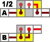
NOT gate (inverter)
A device that inverts the input, as such it is also called an "Inverter" Gate.
| A | NOT A |
|---|---|
| 1 | 0 |
| 0 | 1 |
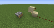
Example of design B NOT gate. Here the input is on and the output therefore is off.
| Design | A | B |
|---|---|---|
| Size | 1x1x2 | 1x2x1 |
| Torches | 1 | 1 |
| Redstone | 0 | 0 |
| Input isolated? | Yes | Yes |
| Output isolated? | Yes | Yes |
OR Gate (?)
Three-input OR gate
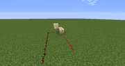
Example of design B OR gate. Input A is on.
A device where the output is on when at least one of the inputs are on.
A simpler version of the OR gate is design A: merely a wire connecting all inputs and outputs. However, this causes the inputs to become "compromised", so that they can only be used in this OR gate. If you need to use the inputs elsewhere, version B is necessary.
Note that design B is a simple inversion of a NOR gate.
| A | B | A OR B |
|---|---|---|
| 1 | 1 | 1 |
| 1 | 0 | 1 |
| 0 | 1 | 1 |
| 0 | 0 | 0 |
| Design | A | B |
|---|---|---|
| Size | 1x1x1 | 1x3x2 |
| Torches | 0 | 2 |
| Redstone | 1 | 1 |
| Inputs isolated? | No | Yes |
| Output isolated? | No | Yes |
| Max inputs | 3 | 4 |
AND Gate (?)
AND gate designs.
Example of design A AND gate. Input A is on.
A device where the output is on when both inputs are on. This behaves in a manner equivalent to a Tri-state buffer, where input B acts like a switch, so that if it is off, input A is disconnected from the rest of the circuit. The discrepancy from real-life tri-state buffers lies in the fact that one cannot drive a low current in Minecraft. (See the Wikipedia article for details.)
An example application would be building a locking mechanism for a door, requiring both the activating button and the lock (typically a lever) to be on.
| A | B | A AND B |
|---|---|---|
| 1 | 1 | 1 |
| 1 | 0 | 0 |
| 0 | 1 | 0 |
| 0 | 0 | 0 |
| Design | A | B | C |
|---|---|---|---|
| Size | 3x2x2 | 2x3x2 | 1x6x5 |
| Torches | 3 | 3 | 3 |
| Redstone | 1 | 2 | 3 |
NOR Gate (?)
NOR gate designs.
Example of design A NOR gate. Input A is on.
A device where the output is off when at least one of the inputs are on. In Minecraft, this is the basic logic gate, implemented by a torch. A torch can have as many as 4 mutually isolated inputs (design B), but 3 can fit comfortably (design A), and all are optional. A torch with 1 input is the NOT gate, and with no inputs is the TRUE gate (i.e. a power source). If more inputs than 4 are necessary, one must resort to the non-isolated OR gate with a NOT at the end (at expense of isolation), or multiple NOR gates, according to the formula A ? B ? C = A ? ¬(B ? C) (at the expense of speed, due to the nested gates).
| A | B | A NOR B |
|---|---|---|
| 1 | 1 | 0 |
| 1 | 0 | 0 |
| 0 | 1 | 0 |
| 0 | 0 | 1 |
| Design | A | B |
|---|---|---|
| Size | 1x1x2 | 3x3x3 |
| Torches | 1 | 1 |
| Redstone | 0 | 5 |
| Inputs | 3 | 4 |
| Inputs isolated? | Yes | Yes |
NAND Gate (?)
NAND gate designs.
A device where the output is off when both inputs are on.
| A | B | A NAND B |
|---|---|---|
| 1 | 1 | 0 |
| 1 | 0 | 1 |
| 0 | 1 | 1 |
| 0 | 0 | 1 |
| Design | A | B |
|---|---|---|
| Size | 3x1x2 | 2x2x1 |
| Torches | 2 | 2 |
| Redstone | 1 | 1 |
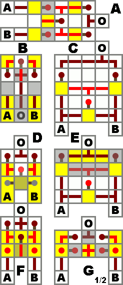
XOR Gate (?)

XOR gate designs.
A device which activates when the inputs are not equal to each other. Pronounced "exor". Adding a NOT gate to the end will produce an XNOR gate, which activates when the inputs are equal to each other. A useful attribute is that a XOR or XNOR gate will always change its output when one of its inputs changes.
| A | B | A XOR B |
|---|---|---|
| 1 | 1 | 0 |
| 1 | 0 | 1 |
| 0 | 1 | 1 |
| 0 | 0 | 0 |
| Design | A | B | C | D | E | F | G |
|---|---|---|---|---|---|---|---|
| Size | 3x5x2 | 3x3x3 | 5x5x1 | 3x3x2 | 5x4x2 | 3x3x3 | 5x2x2 |
| Torches | 5 | 5 | 3 | 3 | 3 | 5 | 8 |
| Redstone | 6 | 5 | 14 | 3 | 12 | 4 | 4 |
| Speed (ticks) | 3 | 3 | 2 | 2 | 2 | 3 | 3 |
| Output direction | fwd. | rev. | fwd. | fwd. | fwd. | fwd. | fwd. |
| Requires levers? | No | No | No | Yes | No | No | No |
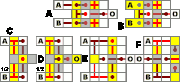
XNOR Gate (=)

XNOR gate designs.
A device which activates when the inputs are equal to each other.
| A | B | A XNOR B |
|---|---|---|
| 1 | 1 | 1 |
| 1 | 0 | 0 |
| 0 | 1 | 0 |
| 0 | 0 | 1 |
| Design | A | B | C | D | E | F |
|---|---|---|---|---|---|---|
| Size | 4x3x2 | 4x3x2 | 2x5x4 | 3x5x3 | 4x5x2 | 4x5x2 |
| Torches | 6 | 4 | 4 | 4 | 4 | 4 |
| Redstone | 5 | 5 | 7 | 7 | 10 | 9 |
| Speed (ticks) | 3 | 2 | 2 | 2 | 2 | 2 |
| Output direction | fwd. | fwd. | fwd. | fwd. | fwd. | rev. |
| Levers required? | No | Yes | No | No | No | No |
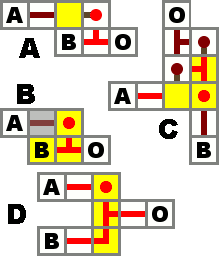
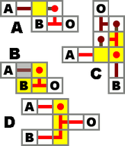
IMPLIES Gate (?)
IMPLIES gate.
A device which represents material implication. Returns false only if the implication A ? B is false, that is, if the conditional A is true, but the consequent B is false.
| A | B | A ? B |
|---|---|---|
| 1 | 1 | 1 |
| 1 | 0 | 0 |
| 0 | 1 | 1 |
| 0 | 0 | 1 |
| Design | A | B | C | D |
|---|---|---|---|---|
| Size | 2x2x1 | 2x1x2 | 2x3x2 | 1x3x2 |
| Torches | 1 | 1 | 3 | 1 |
| Redstone | 1 | 1 | 2 | 2 |
| Speed (ticks) | 1 | 1 | 2 | 1 |
| Inputs isolated? | Only A | Only A | Yes | Only A |
| Output isolated? | No | No | Yes | No |
Latches and Flip-Flops
Latches and Flip-Flops are effectively 1-bit memory cells. They allow circuits to store data and deliver it at a later time, rather than acting only on the inputs at the time they are given. Functions using these components can be built to give different outputs in subsequent executions even if the inputs don't change, and so circuits using them are referred to as "sequential logic". They allow for the design of counters, long-term clocks, and complex memory systems, which cannot be created with combinational logic gates alone.
The common feature at the heart of every redstone latch or flip-flop is the RS NOR latch, built from two NOR gates whose inputs and outputs are connected in a loop (see below). The basic NOR latch's symmetry makes the choice of which state represents 'set' an arbitrary decision, at least until additional logic is attached to form more complex devices. Latches usually have two inputs, a 'set' input and a 'reset' input, used to control the value that is stored, while flip-flops tend to wrap additional logic around a latch to make it behave in different ways.
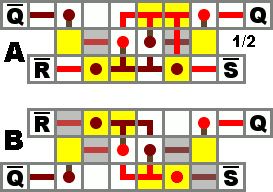
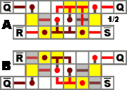
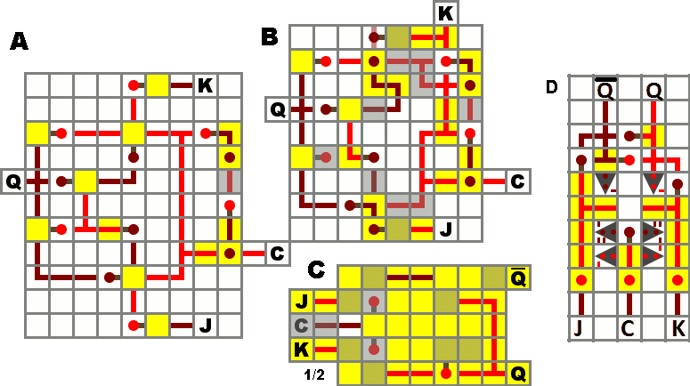
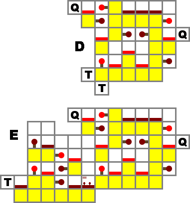
RS NOR latch

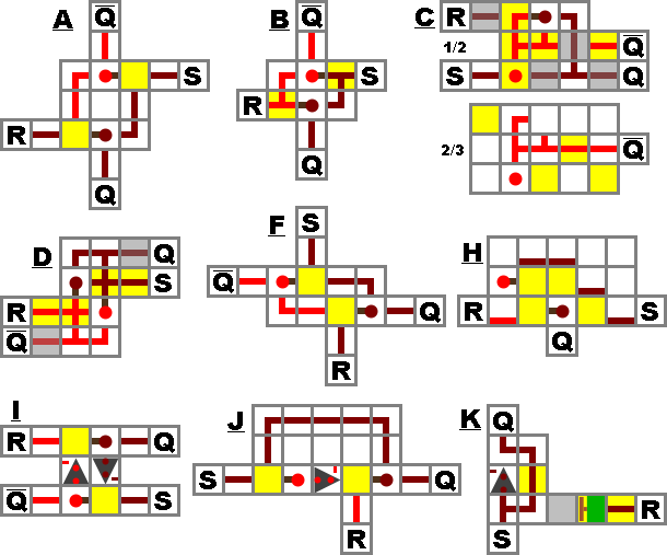
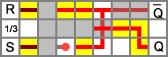
RS NOR latch designs.

RS NOR latch E design.
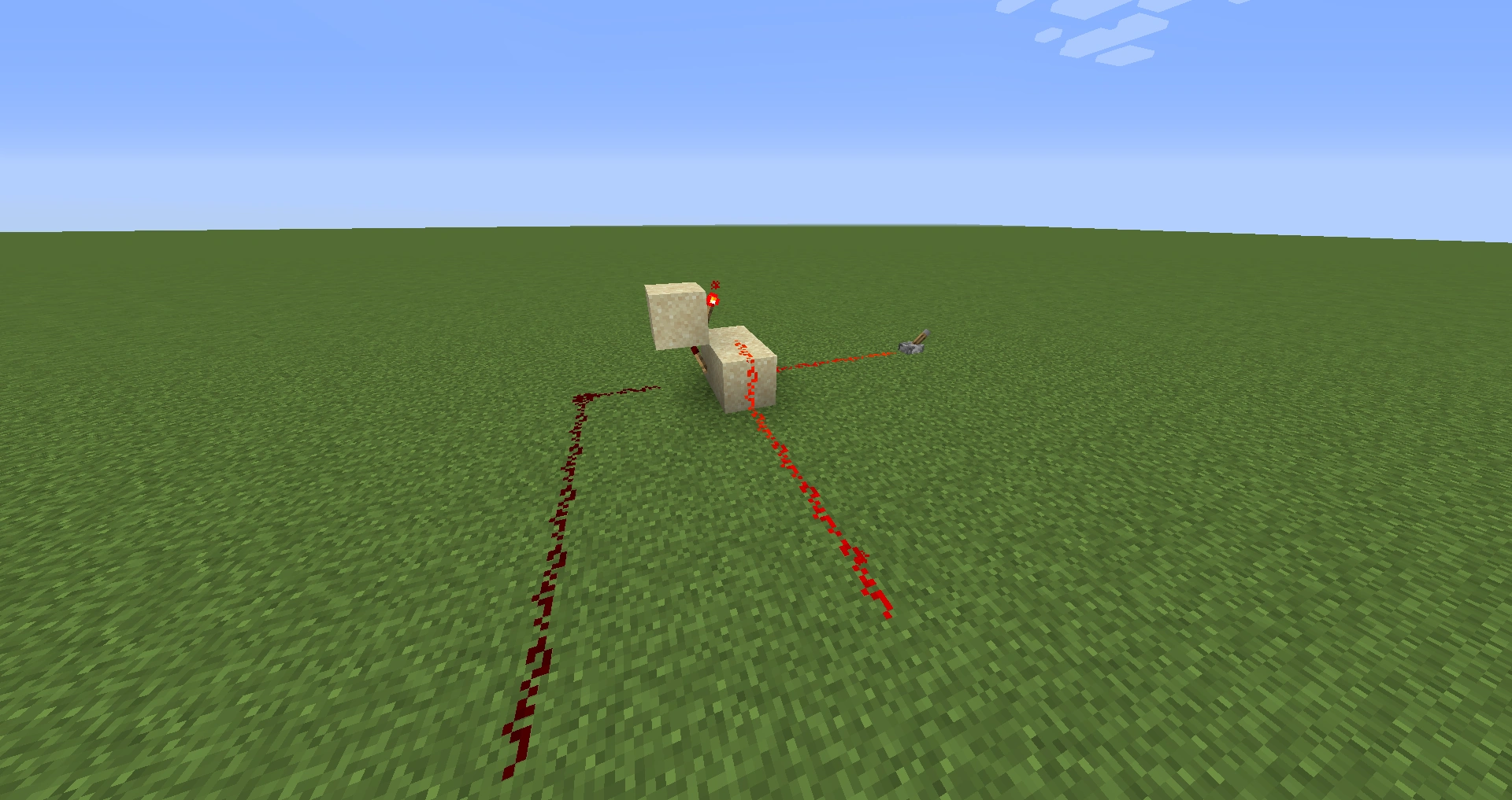
Example of design A RS NOR Latch. Here the latch is in the 'off' state.
Design H, viewed from the side (Source)
A device where Q will stay on forever after input is received by S. Q can be turned off again by a signal received by R.
This is probably the smallest memory device that is possible to make in Minecraft. Note that Q means the opposite of Q, e.g. when Q is on, Q is off and vice-versa. This means that in certain cases, you can get rid of a NOT gate by simply picking the Q output instead of putting a NOT gate after the Q output.
A very basic example of use would be making an alarm system in which a warning light would stay turned on after a pressure plate is pressed, until you hit a reset button.
In the truth table, S=1, R=1 is often referred to as forbidden, because it breaks the inverse relationship between Q and Q. Also, some designs where the input is not isolated from the output, such as B and D, will actually result in Q and Q both apparently being 1 in this case. As soon as either S or R becomes 0, the output will be correct again. However, if S and R both become 0 on the exact same tick, the resulting state could be either Q or Q, depending on quirks of game mechanics. In practice, this input state should be avoided because its output is undefined.
| S | R | Q | Q |
|---|---|---|---|
| 1 | 1 | Undefined | Undefined |
| 1 | 0 | 1 | 0 |
| 0 | 1 | 0 | 1 |
| 0 | 0 | Keep state | Keep state |
| Design | A | B | C | D | E | F | G | H |
|---|---|---|---|---|---|---|---|---|
| Size | 3x3x1 | 2x3x2 | 3x3x3 | 4x2x2 | 7x3x3 | 4x2x1 | 3x2x2 | 1x3x3 |
| Torches | 2 | 2 | 2 | 2 | 3 | 2 | 2 | 2 |
| Redstone wire | 4 | 4 | 8 | 6 | 18 | 4 | 3 | 3 |
| Inputs isolated? | Yes | No | Yes | No | Yes | Yes | Yes | No |
| Outputs isolated? | Yes | Yes | No | No | Yes | Yes | Yes | No |
| Input orientation | opposite | opposite | adjacent | either | adjacent | opposite | adjacent | opposite |
RS NAND latch
RS NAND latch designs.
Since NOR is the basic logic gate in Minecraft, a design for an RS NAND latch is just an RS NOR with inverters applied to the inputs and outputs.
When S and R are both off, Q and Q are on. When S is on, but R is off, Q will be on. When R is on, but S is off, Q will be on. When S and R are both on, it does not change Q and Q. They will be the same as they were before S and R were both turned on.
| S | R | Q | Q |
|---|---|---|---|
| 1 | 1 | Keep state | Keep state |
| 1 | 0 | 0 | 1 |
| 0 | 1 | 1 | 0 |
| 0 | 0 | Undefined | Undefined |
| Design | A | B |
|---|---|---|
| Size | 6x3x3 | 6x3x2 |
| Torches | 6 | 6 |
| Redstone | 10 | 8 |
| Input orientation | adjacent | opposite |
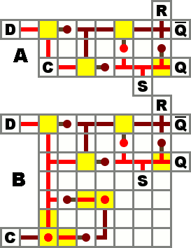
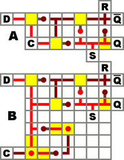
D Flip-Flop
D flip-flop designs.
Side view of a vertical D flip-flop, design C (Source)
Design D (Source)
A D flip-flop, or "data" flip-flop, sets the output to D only on certain conditions. The basic level-triggering D flip-flop (design A), also known as a gated D latch, sets the output to D as long as the clock is set to OFF, and ignores changes in D as long as the clock is ON. Design B includes an edge-trigger, and will set the output to D only at the moment the clock goes from OFF to ON.
In these designs, the output is not isolated; this allows for asynchronous R and S inputs (which override the clock and force a certain output state). To get an isolated output, instead of using Q simply connect an inverter to Q.
Design C is a one block wide version of A, except for using a non-inverted clock. It sets the output to D as long as the clock is ON (turning the torch off). This design can be repeated in parallel every other block, giving it a much smaller footprint, equal to the minimum spacing of parallel data lines (when not using a "cable"). A clock signal can be distributed to all of them with a wire running perpendicularly under the data lines, allowing multiple flip-flops to share a single edge-trigger if desired. The output Q is most easily accessed in the reverse direction, toward the source of input. Q can be inverted or repeated to isolate the latch's Set line (the unisolated Q and Q wires can do double duty as R and S inputs, as in design A).
| Design | A | B | C | D |
|---|---|---|---|---|
| Size | 7x3x2 | 7x7x2 | 1x5x6 | 2x3x5 |
| Torches | 4 | 8 | 5 | 8 |
| Redstone wire | 11 | 18 | 6 | 5 |
| Trigger | Level | Edge | Level | Level |
| Output isolated? | No | No | No | No |
| Input isolated? | Yes | Yes | C Only | Yes |
JK Flip-Flop
JK flip-flop designs.
An unclocked JK Flip-Flop works a lot like a RS NOR Latch. When the input J is ON and the input K is OFF, the output Q is ON. It will then hold that state until only K or both is ON. When only K is ON the Q is OFF. When both inputs are on they will start a race condition. This means that the output will keep changing until one of the inputs is turned OFF (It doesn't race fast enough to burn out the torches).
NOTE: Some of the illustrated JK Flip-Flops to the right don't include the typical inverse Q output. If you want to use the inverse Q then just add an inverter to the Q.
| Design | A | B | C |
|---|---|---|---|
| Size | 11x9x2 | 9x8x2 | 5x7x4 |
| Torches | 12 | 12 | 11 |
| Redstone | 34 | 35 | 22 |
| Accessible Q? | No | No | Yes |
| Trigger | Edge | Edge | Level |
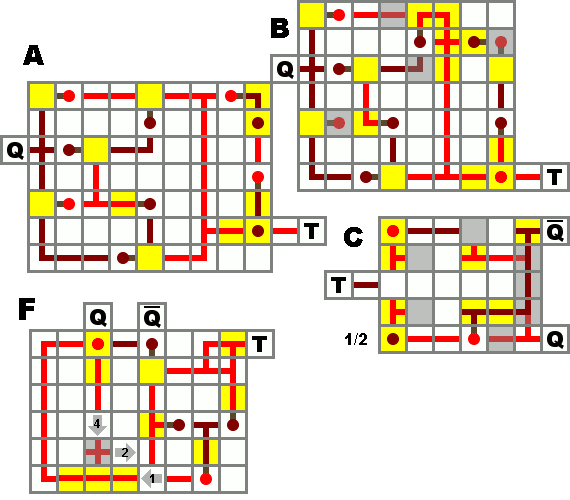
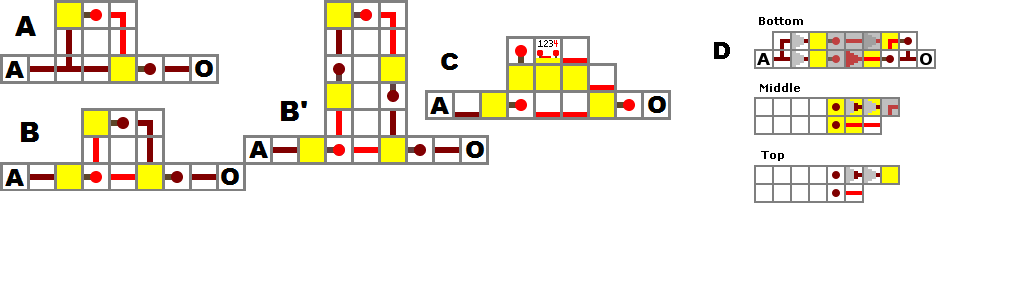
T Flip-Flop
T flip-flop designs.

Side view of vertical T flip-flop designs.
T Flip-Flops are also known as "toggles". Whenever T changes from 0 (off) to 1 (on), the output will toggle its state.
A useful way to use T Flip-Flops in Minecraft could for example be a button connected to the input. When you press the button the output toggles (a door opens or closes), and does not toggle back when the button pops out. (Designs C and D do not have an incorporated edge trigger and will toggle multiple times unless the input is passed through one first.)
It is also the core of all binary counters and clocks, as it functions as a "period doubler", turning two input pulses into one output pulse.
Design A has a large footprint, but is easy to build. It (and B, which is a slightly compacted version of A) is essentially a JK flip-flop with the inputs for J and K removed so that it relies on the edge trigger (right side of the diagram) to keep it in the stable state and only allow a single operation per input.
Design C has a smaller footprint and an easily accessible inverse output, but lacks an edge trigger. If the input is kept high, it will repeatedly toggle on and off, cycling quickly enough to burn out its torches. For example, if the button mentioned above is wired directly to its input, the device can toggle several times before the button shuts off. Even a 4-clock is too slow to reliably result in only one toggle.
Adding an edge trigger by routing input through a separate pulse generator (design B' seems to work best) will prevent this problem, as will any other means of sending it a short (2-3 tick) pulse of power.
Designs D and E are much taller than the others, but only a single block wide, making them good for situations where floorspace is limited. D is level-triggered like design C, which can save space when distributing one input pulse to multiple flip-flops. E has a single block wide edge trigger added on, making it easy to daisy-chain multiple units to create a binary counter or period-doublers for a slow clock. These designs are based on the vertical gated D latch (design C) with the inverse output looped back to the input.
NOTE: Some of the illustrated T Flip-Flops to the right don't include the typical inverse Q outputs. If you want to use the inverse Q then just add an inverter to Q.
| Design | A | B | C | D | E |
|---|---|---|---|---|---|
| Size | 7x9x2 | 7x8x2 | 5x6x3 | 1x7x6 | 1x12x7 |
| Torches | 10 | 10 | 8 | 7 | 12 |
| Redstone | 28 | 29 | 22 | 9 | 15 |
| Accessible Q? | No | No | Yes | No | No |
| Trigger | Edge | Edge | Level | Level | Edge |
Other Electronic Components
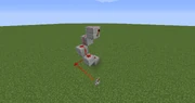
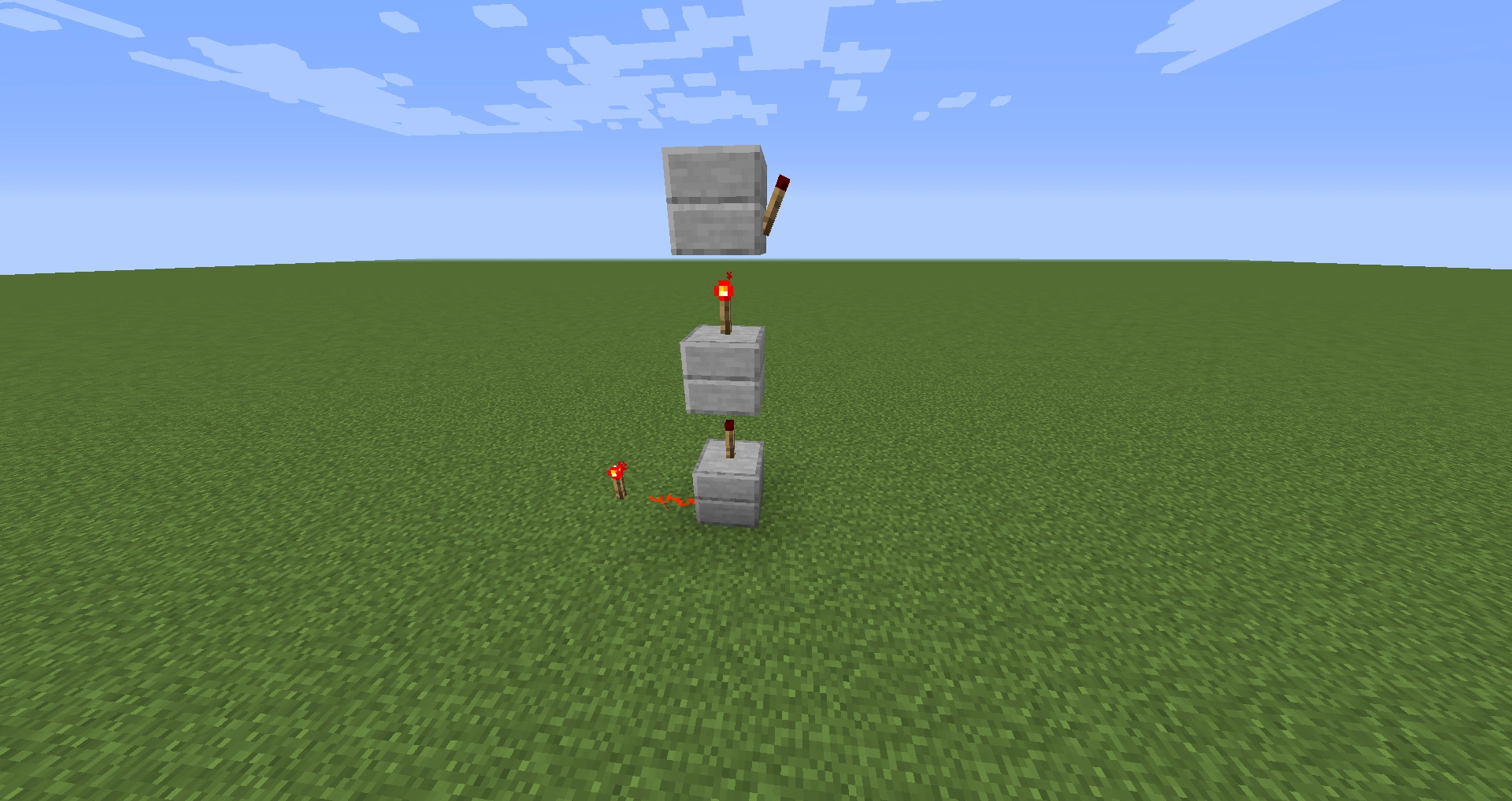
Repeater
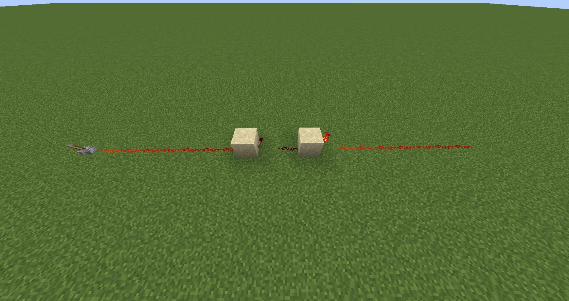
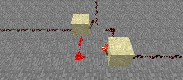
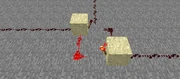
Example of a Repeater
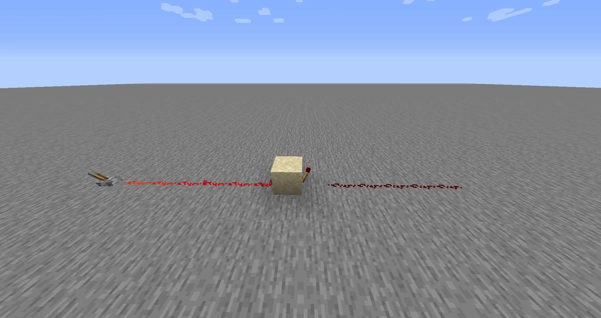
Using two Redstone torches in series can effectively extend your running wire length past the 15-block limitation. As of 1.0.2 (the July 6th update), there must be a strip of wire between the two Redstone torches. Repeaters makes it possible to send long-distance signals around the map, but in the proccess slow down the speed of transfer. To reduce delays, you can stretch out the repeater so that some areas of the wire are consistently in the opposite state, but as long as the amount of Redstone torches, or, effectively, NOT Gates is even, the signal will be correct. In more advanced circuits, repeaters can be used as a semi-conductors; to isolate in- or outputs.
The North/South Quirk
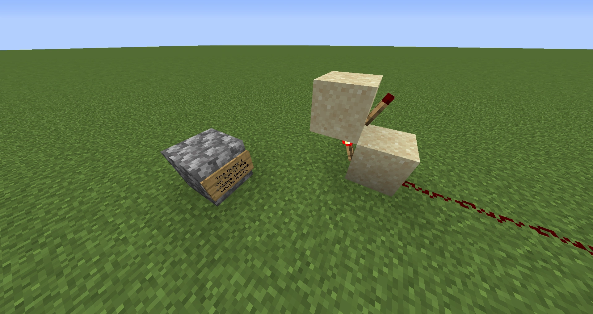
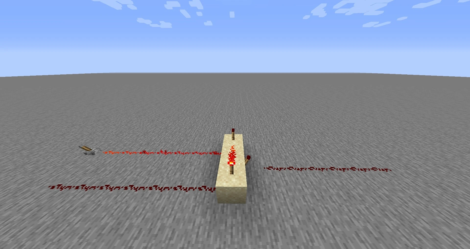
Fig. 1 - The two possible orientations.
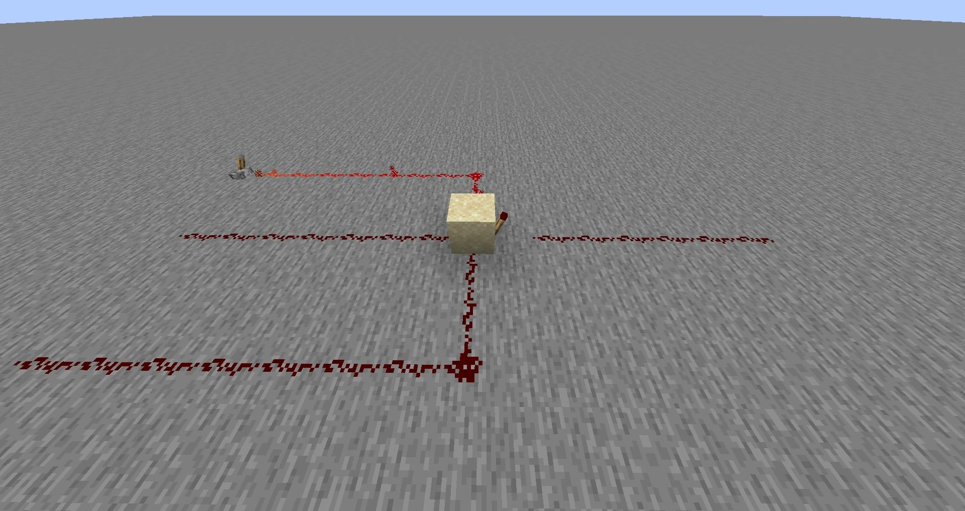
Fig. 2 - Equal-delay inverse outputs.
A specific arrangement of torches which would normally be expected to behave identically to a repeater, causing a 2-tick delay in signal transmission, instead causes only a 1-tick delay. (See figure 1.) When constructed with the torches facing east and west, this arrangement causes the expected 2-tick delay, but when facing north and south, the second (top) torch changes state at the same time as the first, after only a single tick. The quirk can cause unexpected bugs in complicated circuit designs when not accounted for, but it does have several practical uses. For example, double doors require opposite power states, but inverting one signal delays that door's response by 1 tick. The only known way to perfectly synchronize them is with this 1-tick repeater. Another application is in creating a clock circuit (see below) with an even pulse width and period.
Finally, as a generalization of the double-door use, the North/South Quirk can be used to obtain two signals which are always inversely related without the additional 1-tick delay a NOT gate normally causes in the second signal. (See figure 2.) This can be especially useful in circuits where precise timing is important, such as signal processing that relies on the transition of an input from high to low and low to high (on to off and back), for example by sending each of the inverse signals through separate edge detectors (see pulse generators below) and then ORing their outputs.
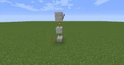
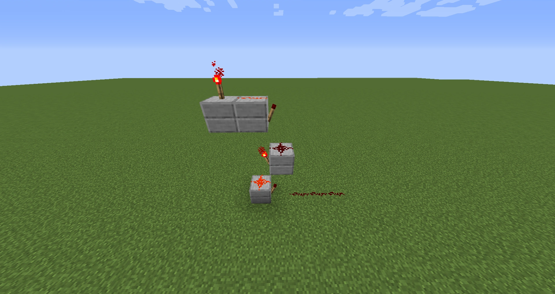
Delay Circuit
Compact delay circuits used to increase signal travel time.
Sometimes it is desirable to induce a delay in your redstone circuitry. Delay circuits aim to do this in a compact manner. These two delay circuits utilize torches heavily in favor of compactness, but in doing so the builder must be aware of the North/South Quirk. For maximum signal delay, construct these designs so that the stacked torches face east and west. For a fine-tuned delay, adjust the design to rotate one of the alternating-torch stacks to face north and south, or add an additional stack in that orientation.
One possible use for delay circuits is to make music. With the introduction of Note Blocks in Beta 1.2, delay circuits can be mixed in with wire and note blocks to create sequences of notes. Here's an example http://www.youtube.com/watch?v=6gPMtzuCKdg
Clock generators
Clock generators and pulsars.

Example clock generator.
Clock generators are devices where the output is toggling on/off constantly. The simplest stable clock generator is the 5-clock (designs B and C). Using this method, 1-clocks and 3-clocks are possible to make but they will "burn out" because of their speed, which makes them unstable. Redundancy can be used to maintain a 1-clock, even as the torches burn out; the result is the so-called "Rapid Pulsar" (designs A and F). Slower clocks are made by making the chain of inverters longer (designs B' and C' show how such an extension process can be achieved).
Using a different method, a 4-clock can be made (design D). A 4-clock is the fastest clock which will not overload the torches.
A 4-clock with a regular on/off pulse width is also possible as seen in design E. This design uses five torches, but can be constructed so that it has a pulse width of 4 ticks by employing the North/South Quirk. It is important that the orientation of this design (or at least the portion containing the stacked torches) be along the north/south axis.
The customary name x-clock is derived from half of the period length, which is also usually the pulse width. For example, design B (a 5-clock) will produce the sequence ...11111000001111100000... on the output.
Pulse Generators
Pulse generator designs.
A device that creates a pulsed output when the input changes. A pulse generator is required to clock flip-flops without a built-in edge trigger if the clock signal will be active for more than a moment (i.e., excluding Stone Buttons).
Design A will create a short pulse when the input turns off. By inverting the input as shown in B, the output will pulse when the input turns on. The length of the pulse can be increased with extra inverters, shown in B'. This is an integral part of a T flip-flop, as it prevents the flip-flop changing more than once in a single operation. Designs A and B can be put together to represent both the increase of A and the decrease of A as separate outputs, these can then be ORed to show when The input changes, regardless of its state.
A pulse generator which causes a short pulse of low power instead of high can be made by removing the final inverter in design B' and replacing it with a wire connection. This is the type used in designs A and B of the T and JK flip-flops (when J=1 and K=1) to briefly place these devices in the 'toggle' state, long enough for a single operation to take place.
Monostable Circuit
Monostable Circuit Design A.
A device that turns itself off a short time after it has been activated. Basically, it consists of a RS-NOR-latch (marked green), which is required for saving the state it is in (powered on/off), and a torch that is connected to itself (marked blue). In "off" state, this torch is always off. When the device is turned on, the torch will start flickering, turning itself on and off rapidly. However, any connected torches will stay in the state they were before the flickering started. After approximately 1.5 seconds the torch will burn out, thus turning off and resetting the whole device.
Monostable Circuit Design Z.
It is possible to extend the time after which the circuit will reset itself by duplicating the circuit marked blue (Design Z). Theoretically the only limit to extending the duration is the time a torch needs to reset itself. If the duration is any longer, the torches will burn out again and again, never allowing the circuit to reset. Furthermore, it is necessary to use repeaters if you add too many of these circuits because of the 15 block limit to redstone signals, thus making the device (a bit) more complex.
Once turned on, the device will ignore any new input until it has reset itself and the burnt out torch is again ready to use. Of course it is possible to omit either the output or the input cable and use one for both purposes.
Vertical transmission
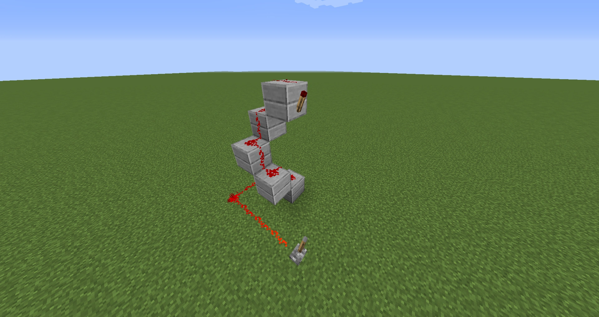
A 2×2 vertical spiral of redstone
Sometimes it's necessary or desirable to transmit a redstone state vertically, for example to have a central control or status for several circuits from a single observation point. To transmit a state vertically, a 2×2 spiral of blocks with redstone can be used to transmit power in either direction, and the spiral is internally navigable (i.e. one can climb or descend within the tower).
If repeaters are necessary, there is a 1×1 design for transmitting a state upward, and a 1×2 design for transmitting a state downward. Internal navigability of these designs inside a 2×2 tower interior can be maintained using ladders.
A 1×1 tower of upward repeaters
A 1×2 tower of downward repeaters
Blink device

Blink device device
Blink device on inside
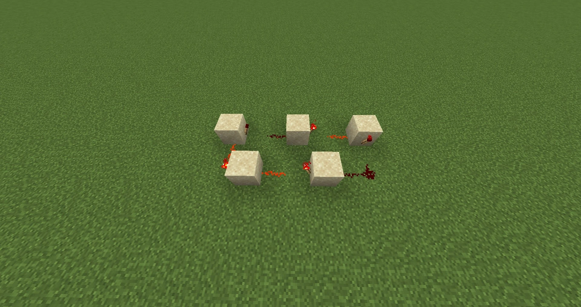
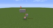
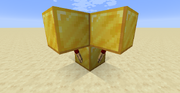
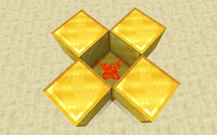
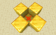
Random short generator
This device creates energy in an irregular sequence.
You can build this device by placing a block with one redstone torch on every side. Place some redstone on top of the block, and place a new block on top of each torch. Then wire it up to different circuits.
A video of this in operation can be found here: [1]
External Links
Related pages
- Redstone
- Redstone (wire)
- Redstone (ore)
- Redstone (dust)
- Redstone Torch
- Advanced Electronic Mechanisms
- Mechanisms
- Traps
- CraftBook (mod) adds integrated circuits and programmable logic chips to SMP
| Help | |||||||||||||||||||
|---|---|---|---|---|---|---|---|---|---|---|---|---|---|---|---|---|---|---|---|
| Menu screens |
| ||||||||||||||||||
| Game customization | |||||||||||||||||||
| Editions |
| ||||||||||||||||||
| Miscellaneous | |||||||||||||||||||