| Archive |
|---|
| /archive |
This page is getting incredibly messy, so I'm going to attempt to do some cleaning and sorting. Anything resolved or not replied to since last year has been moved to the archive. From now on let's try to keep like topics together instead of duplicating, and stick to the new sections =) --Mwr247 23:19, 29 April 2011 (UTC)
Page Layout
For discussions pertaining to the layout of the page as a whole.
Standards
Can we seriously please keep stupid youtube videos off of this page? If we need them somewhere, put them somewhere else.
Redesign
So there were a few topics I archived, mostly old, regarding a redesign to the page as a whole. Fact is this page is just growing so large and cluttered with every possible circuit design, and space isn't being effectively utilized to present them in space saving and efficient way.
For one, I think listing every possible variation of a circuit design is just overkill. Maybe we could have a subpage for each one which would list that, but really we only need one or two on the main page for people to test and understand the logic.
Secondly, I seriously believe we need to deviate away from MCRS for our diagrams, and even more so away from these animated images. MCRS was a great idea and works fine for testing designs, but it really lacks in the way of presentation to people who are new to this (and even some of us old to it). Call me biased but, something closer in design to the master image would be great. maybe we could find someone to make this or convince the MCRS creator to change the standard? As to the animations, they are just horribly annoying, confusing, and lead to worsened standards since few know how (or at take the time) to put them together. In place of these, perhaps some sort of paged content area, where the viewer could hit next and back to navigate between the levels (possible in wiki formatting? I'm sure we could put together a template for it).
Anyways, these are just my thoughts. Anyone else have anything to add? --Mwr247 23:41, 29 April 2011 (UTC)
- Thought I'd throw in my two cents as someone who has just begun to experiment with redstone circuitry. This page is very confusing to a beginner. Clearer definitions of all the different terminology would be appreciated, as well as easily understandable diagrams. This page reads like it was written by a coder for a coder, but not all of us have that background. A basic tutorial would also be a good idea. Thanks -- Pixeldestroyer 22:40, 29 May 2011 (UTC)
- I agree with Pixeldestroyer. Ary31415 01:35, 4 June 2011 (UTC)
- I had a thought, couldn't the more complicated animations, like the multiplexer, benefit from numbered animation layers? It's very hard for a beginner to pick up which symbols are which right away. Also, could that tiny symbol table in the main article be blown up a bit, so the text in the graphic is more readable? I'm pretty good at reading stuff and that text just keeps making me squint at it to read it, which is annoying. BrickVoid 07:54, 13 July 2011 (UTC)BrickVoid
- This is really, 100%, ABSOLUTELY necessary. Even as a redstone veteran, I STILL have a horrible time using this page. Let me expand on what Mwr247 was saying with some of my own thoughts:
- For one, the different circuit designs should be broken into their own pages. There is no need to clutter this page with hundreds of alternative circuit designs. Take a look at how Wikipedia does it for the logic gates article. They summarize the basic info, with links to the appropriate gate-specific pages. Each of those pages describes the implementations in detail.
- Secondly, I agree that we need to move away from MCRS format. MCRS does not support all the current redstone blocks, which forces inconsistent work-arounds. Also, MCRS levers and torches look far too similar. However, I don't think moving to the master image is the best idea. The goal in circuit design is to simplify everything to just the circuit, and the master-image images are more complex than necessary. I am a big fan of Circuit Simulator and its fork by Rek55. This seems to be the only major 2D simulation project currently being updated, and I feel that it keeps enough of MCRS that the diagrams won't change too much, but they will change where they count.
- Thirdly, how to solve the challenge of representing the three dimensional nature of redstone circuitry. I feel this half adder image does a very good job of this. The animated gifs are far too complicated, and since they are constantly changing, it is difficult to see exactly what you are trying to design. I totally agree that the shading nonsense in MCRS (which is very useful in the program, btw) does not lend itself to easy to read schematics.
- I think I'll take a whack at totally overhauling this page this weekend. Stay posted. I should have a link to a sandbox version that I'll be constantly working on soon. --Nick2253 22:58, 19 July 2011 (UTC)
General Descriptions
Compromised
Would it be possible to go a little more into detail about what it means if it's compromised and what adverse affects could result from compromised circuits? Youssarian 19:54, 13 February 2011 (UTC)
- Not necessary if you spend the half-second to build the connection and realize what they mean. That is, when you connect wires like that, they share their ON/OFF state throughout the entire wire, until they get to something their state is independant of, such as the output of another gate. Diodes now can cut allow A while not contaminating your inputs.Firehound 09:42, 14 March 2011 (UTC)
Confusing terminology in Basic Mechanics
It seems to me the descriptions in Basic Mechanics are confusing and possibly using the same word for multiple meanings. In particular:
- Redstone wire is defined as “active” if it is “immediately adjacent to a powered block”.
- “The block under a pressure plate powers itself and all horizontally adjacent blocks when the pressure plate is activated.”
- “Redstone wire beneath [a block with a pressure plate on it] will still be powered, because it is adjacent to the powered block above it.”
This indicates that the rule for redstone wire is indeed that it is active if it is “immediately adjacent to a powered block”, whether or not that block is actually able to transmit power into the block containing the wire (indeed, a block with a pressure plate mounted would not normally be able to transmit power to redstone beneath the block). This all reflects game reality as well.
However, another rule states that “A device, such as a door, a minecart track, or a block of TNT, is activated when an adjacent block is powered.”. Now, a device on top of a block will activate when redstone wire running up to the block is active, which makes sense given that “Redstone wire powers the blocks horizontally adjacent to the ends of the wire only.”.
However, running redstone wire up to the side of a block will not cause redstone wire underneath that block to become active, despite the fact that the block is “powered” (according to the activating-devices definition); the problem is that it's not powered according to the “transmitting” definition.
I therefore propose that the problem is overuse of the word “powered”. For example, I think the first bullet point at the start of my discussion should be that redstone wire is active if it is immediately adjacent to a transmitting block, not to a powered block. I think the section could do with some cleanup in general to strictly differentiate between powered blocks and transmitting blocks. Thoughts? Hawk777 05:47, 18 March 2011 (UTC)
- That's not a bad idea. Ary31415 01:38, 4 June 2011 (UTC)
Redstone General
For discussions on things pertaining to redstone as it relates to circuits.
Changes/Discoveries
Max distance runs
I've done some experiments and found that the farthest you can get from a redstone circuit is 17.5 chunks (281 blocks). In other words, if a clock generator is placed in chunk #1, as soon as you cross the midway point of the 17th chunk it will cease operating. Important to note that it will not begin operating again until you are within 10 chunks (160 blocks). I have only tested this in one direction (North/South) so I'm not sure if a diagonal makes any difference - probably doesn't. That makes the largest redstone circuit design effectively 17x17 chunks (272x272x126). Smidge204 22:00, 9 October 2010 (UTC)
- Excellent work, thanks. I think the maximum circuit design would be 35x35 chunks, though, as long as the player is standing directly in the center. I think this belongs as a technical note on the main article. --TaviRider 17:29, 20 March 2011 (UTC)
- Actually, if the circuit ceases operating at 17 chunk distance and doesn't begin operating again until 10, then wouldn't that make it only 27 chunks? Say you start moving from the far end of the circuit, by the time you read the edge before where you started from stops working, it will only make the next 10 in front of you active.
- This also surprises me since chunks says only the nearest 81 chunks are active. Does this mean redstone circuits across chunks can make the connected chunks stay loaded twice as long? --Sennyotai 06:48, 5 July 2011 (UTC)
- It should be noted though that on SMP servers, there is no limit, We have run a signal to a ticker over 3000 blocks away. Deamon5550 18:14, 8 July 2011 (UTC)
Powering Redstone Through Walls/Blocks
In the article it says it is impossible to power redstone through blocks, but this is untrue. Redstone torches and repeaters can be used to transfer power through walls, but this is so obvious I thought I'd check to see if there is a reason for this omission. Pitzik4 18:14, 5 July 2011 (UTC)
- The power can only be transferred through blocks directionally, but it still can be transferred. I think that part or the page needs a bit of rewriting. FatherToast 18:39, 5 July 2011 (UTC)
Bugs
Block not updating neighbouring devices upon cutting off their own power
When power is channeled into a block removing a wire/repeater next to this block won't update all devices/wires/torches connected to the said block until it's updated by other means. It will look like the block is still being powered yet nothing, in fact, powers it.
Problems with Redstone Torches
Rewrite: I've noticed when a the power going into a torch changes for one tick that the torch will not correctly update the next tick to what it should have been. This can lead to problems with edge triggering and making certain designs that require that have problems. This could be the cause of the T flip-flop E design not working and I believe its why some of my creations do not work properly. On rare occasions like maybe 1/15 or so attempts the torch will correctly update when this happens like it's supposed to but it's unreliable. Also this problem does not occur with redstone repeaters.
Here is an example. (this happens in minecraft but I'm using the simulator to easily explain it) Image:RSTorch EdgeTrig Prob.png A 2-tick edge trigger is attached to an RS Nor Latch to show that the power doesn't affect it even though it reaches it.
So is there anyway to contact mojang on this serious issue? It causes problems for designs using edge triggers and makes certain things either impossible or much more complicated to build. Jrob 17:11, 18 March 2011 (UTC)
- I believe that the torches are behaving as designed. They need to be powered for at least one full tick before they will deactivate. I consider this one of many practical limitations that keep redstone from causing too many block updates.
That said, if you still want to report it to Mojang, post it on [Mojang's GetSatisfaction page|http://getsatisfaction.com/mojang]. --TaviRider 17:28, 20 March 2011 (UTC)
- I guess this makes sense, but there must be some way to fix edge triggered to behave properly. Maybe all redstone devices including wiring should only change state at the begginging of a tick, this way nothing will get powered half way through a tick leading a torch to not recognize that first tick.
Jrob 21:43, 23 March 2011 (UTC)
- I have run into the same issue with design E some work some the edge trigger fires too fast. So I redesigned the edge trigger to be adjustable. Image:Vertical_pulsar.gif The arrow is a relay and on setting 2 has always worked for me when the one in design E failed me. --Yssaril 22:53, 23 March 2011 (UTC)
Technical Questions
Wiring a vertical redstone circuit
How do you take an input and use it to power blocks that are higher or lower than the lever/button/pressure pad? I'm attempting to construct the stairs mentioned in the trapdoor uses page. Soulblade0619 23:49, 2 June 2011 (UTC)
- You just place blocks in a stair shape, put redstone wire going all the way up them, wire it to a switch, and put the trapdoor on the sides of the blocks. I have a picture but I don't know how to upload it. If you tell me how I'll upload it for you. Ary31415 02:00, 4 June 2011 (UTC)
- I did just that. I made a stair shape of blocks, put wire on top of them and put the trapdoors on the side, and then put a lever on the block one to the left and one block up. The lever only activated the first and the second trapdoor (the second wire doesn't get power for some reason).
- Do you think it has something to do with the fact that the staircase blocks are brick? Soulblade0619 00:07, 6 June 2011 (UTC)
- It's about distance, the wires can only go for so long before they no longer 'activate'. because of the stairs you used up a lot of this distance before it reached the end of the trapdoors. Neopopulas14 June 2011
I figured out how to upload a picture. You do what the picture shows and put the trapdoors on the left sides of the blocks. If your staircase is really long, you will need redstone repeaters to extend the length a current can travel.
How to wire the staircase
Ary31415 13:57, 15 June 2011 (UTC)
Gate Designs
For discussions pertaining to the gates and their designs.
Design Standards
Missing Logic Gate (For Completeness)
The truth tables made me notice the list of gates is incomplete. Some are on the list or are input-switched duplicates of those on the list: nor; not a; not b; xor; nand; and; xnor; A implies B; B implies A; or. Some are trivial: always off; b; a; always on. That leaves two possibilities (one and it's input-switched version): b and not a, a and not b. I know it's a simple gate, but it should be included for completeness; It's basically just invert one input, join inputs, invert if anyone can put together a diagram (or an 'and' gate with one input inverter removed).
JK to T flip flop
Is it worth noting that a JK flip flop can be used as a T flip flop by connecting both J and K to a single input? I verified this myself with design C, with the clock either always on or just connected to the same input as J and K. I realize that most flip flops can be used as other types but the simplicity of creating a T from a JK makes it the most useful I think.
- Is that really all that useful? For any given layout style, the TFF is a bit smaller than the JKFF; it seems counterproductive to eat up more space building a JKFF only to use it as TFF. Hawk777 03:40, 28 April 2011 (UTC)
New Designs/Discoveries
New XNOR Gate
I needed a XNOR gate which was smaller and higher than the usual one, and ended up stacking two AND gates (the top one becoming "NAND" because of the bottom torches). It's only one column smaller than the usual, but I guess one is quite alright on a scale of five.
I'm not sure if it's really 'new', and if the design is clear, but it seemed to differ from the one presented on the page, so I thought I'd just as well share it here. Archasylum 09:45, 5 July 2011 (UTC)
New XNOR Gate
I've made a new design of xnor gate using repeater :
I think it can be optimised, and since it the first xnor gate using repeater, it may have a potential. --Ceandros 00:19, 11 July 2011 (UTC)
Another Pulse Generator
This Pulse Generator uses minecarts and rails to make a pulser. Just push a minecart on to the powered rails to activate the pulser.
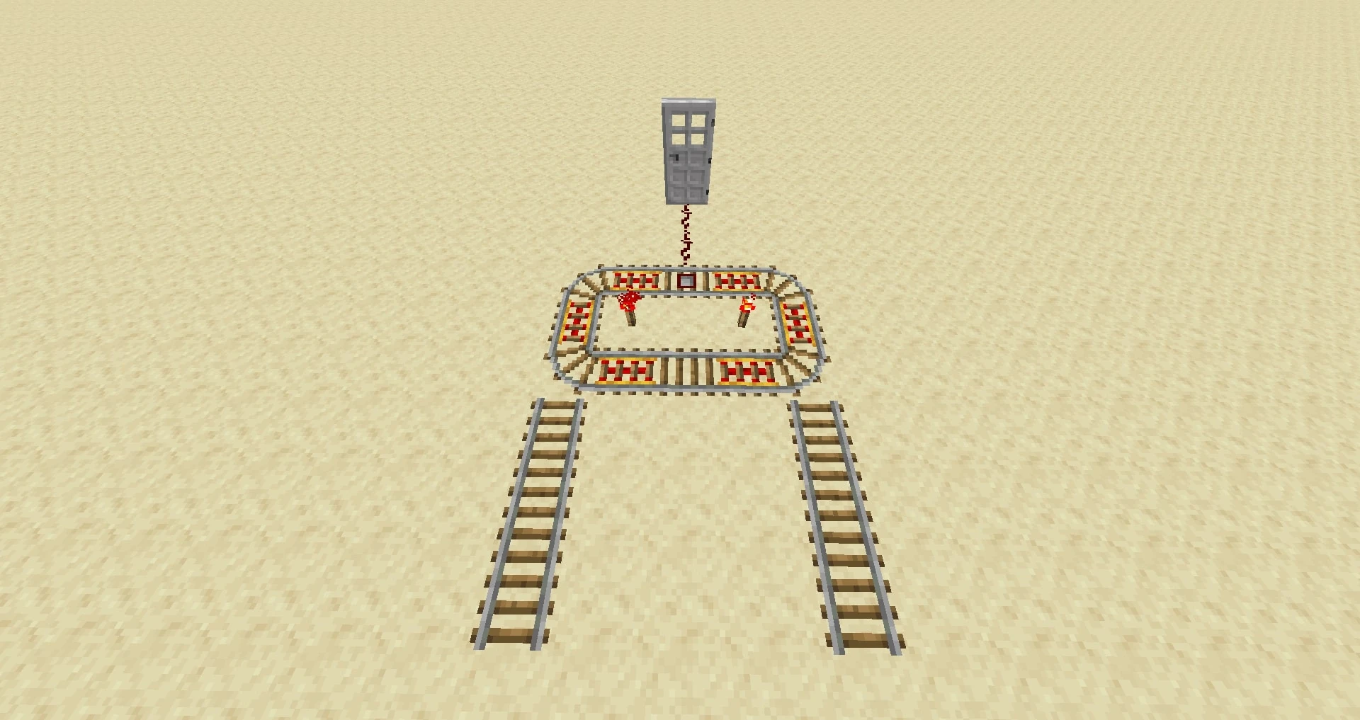
The Second Version involves the redstone repeaters on one side to be on the setting 3, 3, 1 or 3, 2, 2. This way, both sides have and equal time beteen the the closing of one and the opening of the other.
Maybe, it's possible to create a more compact version of this.
Assisstion 11:15, 22 June 2011 (UTC)
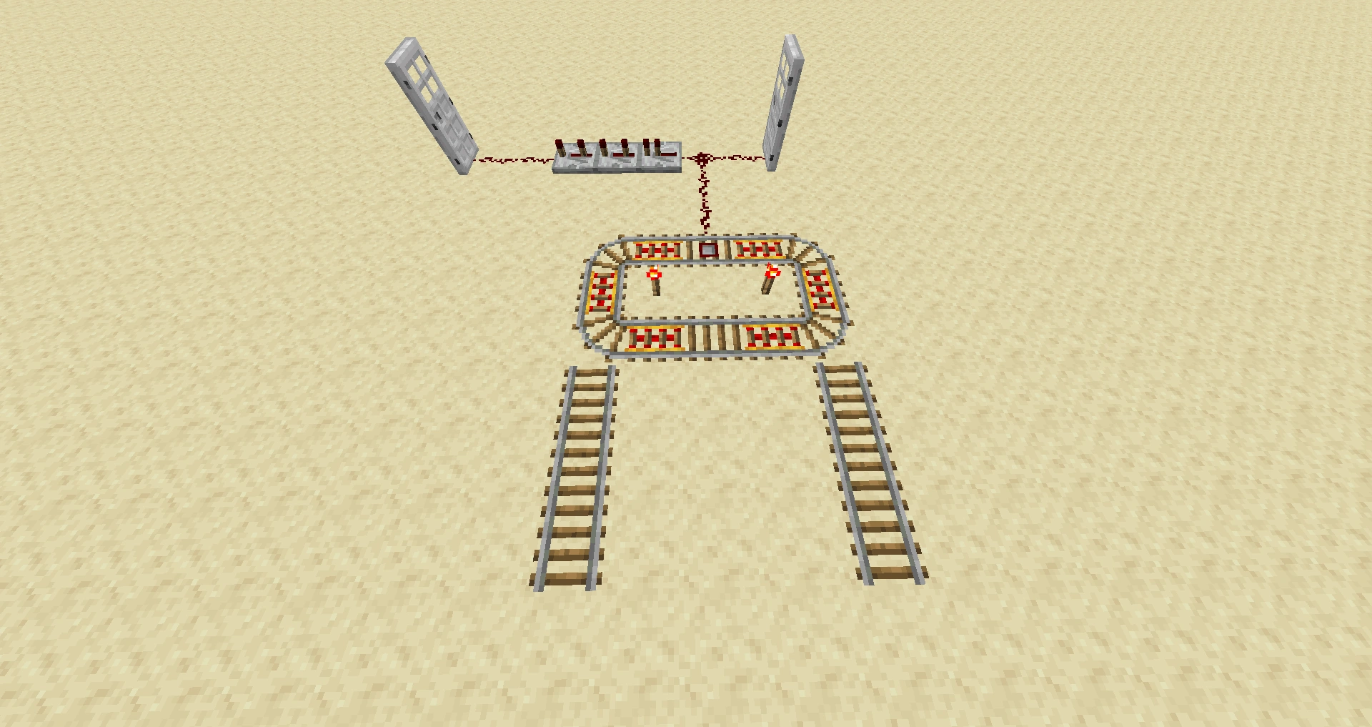
- I like this idea, a lot. In fact I just used a variation of it to solve a problem of mine with my latest insane contraption. However, your design does have one fundamental flaw. An endless loop will eventually accelerate carts up to max velocity and fail, destroying the cart.
- This is easy to fix however. Instead of an endless loop, make a single line terminating in a ramp on each side. This way when the cart reaches the end, it goes to the top of the ramp, stops briefly, and then rolls back down the ramp. Use accelerators as necessary to make sure the cart never truly stops. Doctor Zuber 02:48, 5 July 2011 (UTC)
More Compact Pulse Generator
I made a smaller, more configurable pulse generator that uses Repeaters. The shortest setting at the repeaters is 3 ticks (anything less appears to give no pulse), adjustable to 8. It could be modified to give a longer pulse by adding more repeaters.
It is smaller than the current smallest on the page, but is also two blocks tall.
Was unable to upload the image, here is a link: http://i.imgur.com/DhSEQ.png
SomeKindOfOctopus 02:10, 8 May 2011 (UTC)
Update with new Redstone Repeaters?
So is anyone going to update these designs/schematics with the new Redstone Repeaters? I'm sure that some of these can be simplified a bit using the new repeater blocks. SpikeX 19:50, 24 February 2011 (UTC)
- I've already tested and proofed some smaller designs for the RS NOR/NAND gate designs incorporating the new delay/repeater/diode block (2x3x1 and 3x5x2 respectively), and other gates could no doubt benefit from their inclusion (clocks and pulsars being some of the most significant). I think we need some official diagram image representation and then get to work on rebuilding some of these =D --Mwr247 20:50, 25 February 2011 (UTC)
- 1.3 is the first version I have played, and I've noticed some of these designs no longer work, particularly when they involve edge triggers. The power will come on and off too quickly to trigger the torch. The wonderful thing about repeaters is that adding one to one side of the non-triggering edge trigger seems to always work. It's been a while since I did circuits and this is helping me remember my lab class... but would greatly appreciate updated circuit diagrams with repeaters nonetheless!
- Joren (talk) 22:23, 1 March 2011 (UTC)
Compact T Flip-Flop
I was trying to make a T flip-flop more compact using repeaters, and this is the result:
Image:6x4x2_tflipflop.PNG
Is this worth adding to the wiki?
Output is at (3,3), and (4,7).
Input is to block (3,2).
RT-073 20:20, 4 March 2011 (UTC)
Edit: It seems to only work when the button is to the north or east of the flip flip... Has anyone figured out if the south-west rule affects repeaters?
RT-073 19:03, 7 March 2011 (UTC)
- One of the few TFFs I've managed to get working (being a beginner). The (4,7) output flickers on state changes, but the (3,3) output seems stable. The limit on the orientation is odd, but it's still a good design to me!
- Ebkrem 17:46, 6 July 2011 (UTC)
New T Flip-Flop design
I found a new design for T Flip-Flops. It is really small: only 6x6x2 ! I added it to the page as "Design G" but I am not allowed to upload files so it is currently a link to an external image. If someone could upload it and add it as a thumbnail under the other designs... :)
- Please sign your statements so we know who you are ;) Anyone want to test this for functionality? --Mwr247 23:19, 29 April 2011 (UTC)
New Monovibrator Design
So I came up with a new monostable circuit design that doesn't rely on torch burnout, would this be something that we should include on this page? Image:Monovibrator.gif --cptroot 12:06, 26 February 2011
Vertical Flat Design Nonfunctional
Having implemented the circuit shown here with a slightly longer than normal delay (12 ticks) I found that it in fact does not work as desired. It lacks the RSNOR-latch present in other designs and thus if given a momentary input (say from a button) the output signal will switch off, rather than staying on until the delay finishes. See this screenshot. This design does work if the input signal is constant, however, as it will shut itself off without receiving a 0 input. The device is only monostable in that it will truncate the input signal, but not in lengthening a pulse.
...Likewise, neither does the compact version work as intended. T and Q touch directly, thus ruining the circiut.
Nevermind, I'm an idiot. I had a test button to check it where I could see it, and it was providing input in the back end of the circiut.
--Draco18s 23:55, 5 May 2011 (UTC)
I'm pretty sure your not an idiot, the compact monostable design on the page is faulty, its short-circuited as you said (Input connects directly with output.) I tried to use it when it was lever-powered and was powering a AND gate and I found that it burns out. I was able to make a simple correction on Minecraft by putting a block over the redstone adjacent to Q, but someone still needs to shade that block with editing software. --Weesplat 16:28, 30 June 2011 (UTC)
I fixed the compact monostable circuit but it will still burn out if you do not have the repeater on the 3 or 4 setting. Also worked on the vertical monostable circuit a bit and made it a bit smaller. Testing showed it worked with a lever and a button so pulse or constant power you will still get a short pulse when power is applied. Cadeff 02:18, 6 July 2011 (UTC)
Compact Monostable=
I just finished testing out and putting into use a highly compact and versatile monostable. The 3x3x2 design only has 1 or 2 torch delay. Adding extra repeaters wont make it much wider and the extention can be kept at one high.
Another advantage is that the T can be put on any of the redstone wire one the top side and the Q can be pulled off any of the bottomside redstone.
The obvious disadvantage is that the output is Q instad of Q. It was unintentional but helpful for me since this was to run a pair of doors and I had wired them up backwards for access reasons. Sennyotai 22:18, 26 June 2011 (UTC)
Built on this design for slightly more compact design.
Cadeff 00:53, 5 July 2011 (UTC)
Two-Way Repeater
A while back, I created a new type of redstone circuit (as far as I can tell) which acts as a two-way repeater, essentially serving as an elongated strip of redstone. Unlike normal repeaters, which only work in one direction, this circuit allows a signal to be sent through it from either side. It does not have a traditional input or output, but rather two spots which serve as both input and output, depending on what is attached to them. Whenever either one of them is receiving power, the other one is also receiving power. Whenever one of them is off, both are off.
Also, this circuit even tells you the direction the signal is flowing. Of the two torches which appear unlit in the diagram, whenever the circuit is powered, one will be lit. It will be the only lit torch in the circuit, and it will face the direction the power is moving. Thus, if there is an input from A, the bottom-right torch will be lit. Image:Two way repeater.gif In short, the primary purpose of this circuit is to simulate the function of redstone wire without restricting signal direction like a repeater, but it also happens to indicate which direction the signal is flowing.
Anyway, can I have some feedback on whether or not this should be added to the main page? Sorry, I posted the above without signing. Tamugetsu 18:07, 10 March 2011 (UTC)Tamugetsu
- Is there a more compact version of this using the new repeater blocks? --Balu 11:15, 12 June 2011 (UTC)
Redstone Repeater XOR Circuit
I've come up with a new 4x3x3 XOR design using the properties of the new (1.3_01) Redstone repeaters; I wasn't sure of the repeaters graphic but its easy to identify. Image:XOR.gif --Dingmatt 22:24, 28 February 2011 (UTC)
Binary Counter
I have a binary counter set up that seems pretty simple... It's just a counter, a couple T Flip Flops and some AND gates. And instead of drawing out a diagram for every single piece (it is more than a few, I assure you), you could show how the outputs of the pieces should be connected. It's pretty simple once you have the T Flip Flop, Counter and AND gates down.
- Counter connects to the T Flip Flop (A), our 1 value, and presto, you can count from 0 to 1.
- The output also goes to the next T Flip Flop, (B). This is our 2's slot. You know have a binary counter that goes up to 3.
- The output from A and B go into the AND(a) item. The output from that AND(a) is sent to T Flip Flop (C), our 4 column. It is important that the output from A and the output from B are the input to the AND(a) gate. If you invert to extend the length, invert back again. Also, the output from AND(a) must be the input to C. I can't stress this enough.
- Now that you can count up to 7, it is time to add the next piece. You use the outputs from sources AND(a) and T Flip Flop(C), and plug them into the next AND(b). The output from that connects to T Flip Flop(D). You can now count to 15.
That's as far as I've gotten, but you could follow the same pattern and potentially make it longer. The problem is, I use a 5-timer and the 8 column is *just* changing by the time the 1 column changes for the next number. You would have to have a timer that runs even longer than that. Or condense the counter somehow that I overlooked this early in the morning, so that there isn't so much delay.
Please respond with any comments, questions and concerns. -unsigned comment by Chevnoir 12 Nov 2010
- Starting to build this with T-flop design E (edge triggered). What T-flop design are you using, FYI? --JellyfishGreen 12:02, 29 November 2010 (UTC)
- I have successfully made a 35 bit Design E t-flip flop counter that when wired to tick once a second, will last a year before resetting, however this was simply by daisy chaining them together without any AND gates. May I ask, what is the significance of the AND gates and why are they needed for the design? --Crozone 12:25, 7 February 2011 (UTC)
- This is brilliant, by the way. Mizusajt 07:44, 13 February 2011 (UTC)
- I have successfully made a 35 bit Design E t-flip flop counter that when wired to tick once a second, will last a year before resetting, however this was simply by daisy chaining them together without any AND gates. May I ask, what is the significance of the AND gates and why are they needed for the design? --Crozone 12:25, 7 February 2011 (UTC)
NOR Gate
It's worth noting that a NOR gate with an unlimited amount of inputs is possible with the repeaters. Just use an AND gate to merge the inputs of an inverter after the repeaters. --ZeDingo 08:24, 28 May 2011 (UTC)
Boat T-Flip Flop
I found a T-flip-flop using a boat on Youtube Minecraft - Boat Memory. I was able to shrink it to 6x5x3 (4x3x2 without conting the walls+floor). It only works counter-clockwise. The original and the 6x5x3 version have a flashing output while the input is on. I fixed that by expanding it to 7x5x3 (5x3x2 without walls+floor).
sDww WDPw wwww w=water, W=water source, D=door, P=pressure plate(with output underneath), s=sign or pressure plate WDwww wDPsw sWwww
The upper Doors have to have the hinge on the upper left side (lower left if the inputs are reversed to each other) and the lower doors have to have the hinge on the lower right side. Don't forget the walls and the ceiling. Input is best done by laying redstone wire on the ceiling next to the doors. The mechanical design is obviously slower than an electrical one. The pro is that its small and can be put side by side sharing the walls. Stacking is problematic because the ceiling has holes.
New RS NOR latch
http://www.reddit.com/r/redstone/comments/i9534/3x2x1_clock_rs_nor_latch/ Can someone add it because I have no idea how to make the diagrams or assign it a name. --Ft975 15:41, 2 July 2011 (UTC)
New Piston Designs
D flip-flop memory
Piston D flip-flop
Is anyone here looking into new designs using pistons? There's the clock already, but I think some of the memory devices could be made smaller using them. I've got a d flip-flop worked out, but the input is still a mess at this point. Rhilenova 20:28, 2 July 2011 (UTC)
Main clock
Starter with monostzable circuit
I am :) Here's my result:
A Tempoary 1-clock:
Simply supply power to the monostable circuit, and you get a 1 clock that lasts for a time you can set by the delay line, and is OFF the rest of the time.
--Fred7714 20:32, 4 July 2011 (UTC)
Further Compacted T-flip flop
I recently discovered this on youtube, and have yet to find a more compact design, so I believe this should be added to the Wiki: [2] Thtredstonegui 08:51, 20 July 2011 (UTC)
Design Issues
T-flip flop design F is NOT a T-flip flop!
I've tested the design. Once it recieves a fixed input, the output pulses on and off like a clock. This is not what a T-flip flop is supposed to do! --Munton 14:34, 13 March 2011 (UTC)
- Seems the diagram is missing, but the table and body still reference it. Should be removed? --Mwr247 23:19, 29 April 2011 (UTC)
- No. Don't remove it. Design F is a different type of flip-flop known as a level-triggered flip flop. To use it like a normal flip-flop, just hook t-input to the output of an inverter and a repeater(set at 4) in parallel. --Zonedabone 02:48, 1 May 2011 (UTC)
- Don't remove it? It's a single sentence that's referring to a design that isn't even explained anywhere at all! If someone can look at the Redstone circuits page and tell me how to build an F-design flip-flop then I'm all for keeping it on the page. If not, I vote to remove it. DannyF1966 00:06, 5 June 2011 (UTC)
- No. Don't remove it. Design F is a different type of flip-flop known as a level-triggered flip flop. To use it like a normal flip-flop, just hook t-input to the output of an inverter and a repeater(set at 4) in parallel. --Zonedabone 02:48, 1 May 2011 (UTC)
XNOR A not working
I've successfully built all the other gate types, but XNOR style A isn't working for me. It's behaving like AND instead of XNOR. Can someone confirm that the gate diagram is correct? --TaviRider 19:03, 16 October 2010 (UTC)
- I cannot manage to reproduce any of the XNOR gates. Do any of them work? --bazzaNZ
- I was able to get XNOR A to work. For XNOR B, it seems that the direction that the switches face matters. --TaviRider 01:05, 6 March 2011 (UTC)
(fixed and improved !) T-Flip-Flop design G - missing Redstone
I built the T-Flip-Flop G as shown and it didn't work. There is a redstone wire missing on top of the top right block. If it's placed it works. --Phoenix IV 12:42, 30 April 2011 (UTC)
- I simply edited the diagram by hand but I don't want to change the link in the article: http://img19.imageshack.us/img19/4817/tflipflopg.png Can it be used like this? --Phoenix IV 13:06, 30 April 2011 (UTC)
- Hi there, I'm the one who added the design G.
- It works only if there is a button on the bloc where there is the 'T'. Adding a redstone wire on the top of this bloc makes it works everytime.
- I reduced the size to 6x5x2 and I have uploaded a new picture of the layout.
- And can someone upload the picture http://ploader.net/files/7e8b686f228e6adae37b781224e4fb57.png to put it as thumbnail? I do not have the rights to upload a file...
- --Refreshfr 17:25, 7 May 2011 (UTC)
T-flip flop design H is not very stable, and could be smaller
I've built quite a few of these over the last couple of days (like 20 of them). About 30% do not function correctly when built to the schematic. If the left-hand repeater is set to 2 ticks, rather than 1, it seems much better; so far every unit works correctly. Also, the design can be reduced to 6x3x2 quite easily. http://img20.imageshack.us/img20/8686/tffhrev2.png --DaftasBrush
- I tried to build the design H but it's not a very good T Flip Flop. Not enough stable... --Refreshfr 17:12, 7 May 2011 (UTC)
- I also tried this design. I even tried your variation. Neither appears to work. Doctor Zuber 19:36, 5 July 2011 (UTC)
OR, NOR, and XOR
It took me a while, but I think I finally found out what each does:
- OR - If any input is powered, power the output:
- If both inputs are on, do power the output
- If either input A or input B are on, do power the output
- If both inputs are off, don't power the output
- NOR - If both inputs are not powered, power the output:
- If both inputs are on, don't power the output
- If either input A or input B are on, don't power the output
- If both inputs are off, do power the output
- XOR - If either inputs are powered, but both are not powered or un-powered, power the output:
- If both inputs are on, don't power the output
- If either input A or input B are on, do power the output
- If both inputs are off, don't power the output
Cool12309(T|C) 22:23, 28 May 2011 (UTC)
Could someone explain how design B for the OR gate can accept 4 inputs?
Oey192 02:41, 8 June 2011 (UTC)
NOT SCHEMATIC ISSUE
There is an issue in the schematic for the NOT(invertor) gate, the issue is that it shows the following 4 blocks:
[A][AIR OVER BLOCK][AIR OVER TORCH][B]
The schematic should be:
[A][WIRE OVER BLOCK][AIR OVER TORCH][B]
I have personally verified this issue and submit that we need to change it picture of the schematic.
Diagrams
Question: Where should I put my multiplexer diagram and paragraph? What section? Je007 20:07, 30 June 2011 (UTC)
Shortened XNOR design
I could be wrong be wrong here, but in the Logic Gates section, couldn't the XNOR logic gate be shortened by 2? by removing all three the right hand redstone torches. Essentially just the XOR design above it but with it's two right hand torches replaced with normal redstone. R3sistance 04:32, 29 May 2011 (UTC)
Button-powered blocks
The article says buttons only power the block on which they're mounted, not the block they're actually in. I believe buttons do in fact power the block they're in as well as the block to which they're mounted. I just tried it in Beta 1.6.6. I don't know if this is a recent change, but I think the article should be updated. Thoughts? --Schufty 17:12, 2 June 2011 (UTC)
- Buttons do power the block they're in. I just tried it a minute ago and I had done it in 1.5 too. Ary31415 02:03, 4 June 2011 (UTC)
Rapid Pulser not work well for SMP
If you are on a good running server there still very slow and a 1/4 clock is faster, but on a very bad server side lagging server these are unusable.
XCMods - Helping Minecraft users get the best out of the game. 22:26, 12 June 2011 (UTC)
Awesome!
I designed the T flipflop H/J design. It's really great to see that other people have played with it: replacing my graphic and investigating various gotchas. I'm honestly pleased. go minecraft!
Added T Flip-Flop K
It's a simple design that hasn't been compacted yet, allowing for people to see exactly how it works. Enjoy! Elite6809 (talk) (forum) 19:15, 14 June 2011 (UTC)
- Sorry, but I don't think it makes sense to add designs which are not "better" than the current ones. There are infinite ways to build such flip-flops. "Just one more" without a special value would make a confusing list and not a worthwile wiki.--Binoro 00:19, 9 July 2011 (UTC)
1.6.6 clocks not working
I am running it on Max FPS, anything else lags too much. Anyway, I find that NO clocks work consistently. Even the tried and trusted redstone torch 5-clock will arbitrarily have all 5 torches burn out, never to come back on. can anyone else confirm this? I even have a 5-clock where you see two torches in a row off. Um? Any help on this, and should it be added to the article. Bobbobbob 05:37, 1 July 2011 (UTC)bobbobbob
I have several clocks running in my world, and none of them are experiencing these problems. You mentioned lag: could your computer be the problem? KKPie 15:47, 1 July 2011 (UTC)
I have noticed in-game that using design B of the D Flip Flops section has a bit of an error when the input is 0 and the user activated the edge trigger. It sets the output to 1 for a brief moment sometimes before going back to 0. Scythesabre 03:51, 2 July 2011 (UTC)
Pulse limiters and Monostable circuits
After looking at these two are they not the same thing? It appears that the section on pulse limiters needs removed completely as it is duplicate to monostable circuits. Cadeff 23:56, 5 July 2011 (UTC)
Sock-Shoe Redstone Circuit?
When working with pistons, one often finds that you need to activate one wire ("put on the sock"), then the other when the input powers on ("put on the shoe"), and deactivate the second wire ("take off the shoe") and deactivate the first wire ("take off the sock") when the input powers off.
I found a neat solution involving four repeaters. It was something like this:
 | Input
 |4
 #>#
1V V1
 #<#
 |4L-- Shoe
 |
 |--Sock
where the numbers next to the arrows represent the delays. The arrows are repeaters. I originally got this design from Docm77, who got it from TheReverendworm. Could someone come up with a better name for this, and put it on the wiki? Elmach2MN2 04:26, 14 July 2011 (UTC)